Photo Gallery
DC-DC Buck Boost Converter Teardown
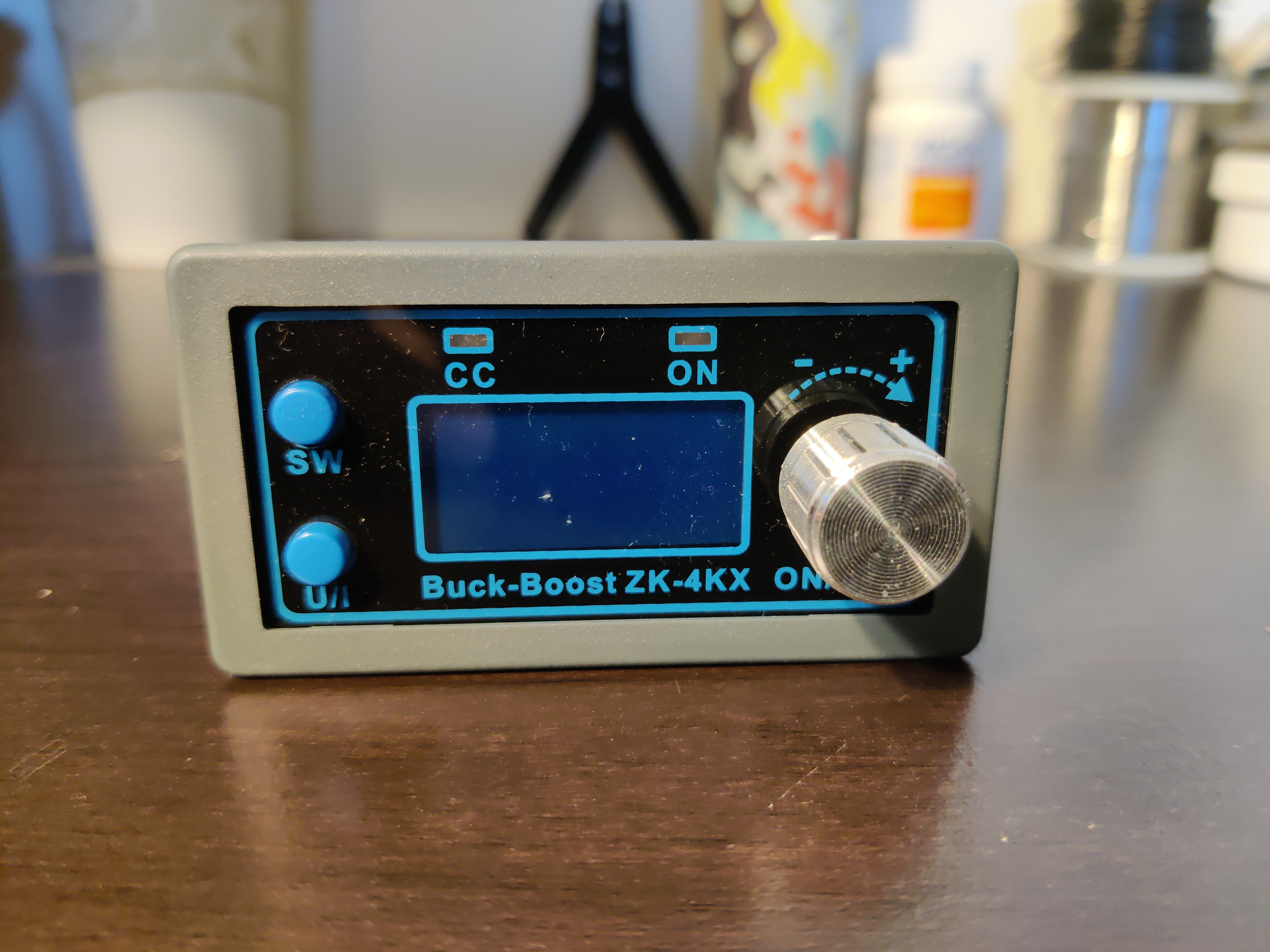
IMAGE 01
Initial Unboxing
Module arrives in anti-static packaging with protective foam. Note the compact form factor optimized for breadboard prototyping.
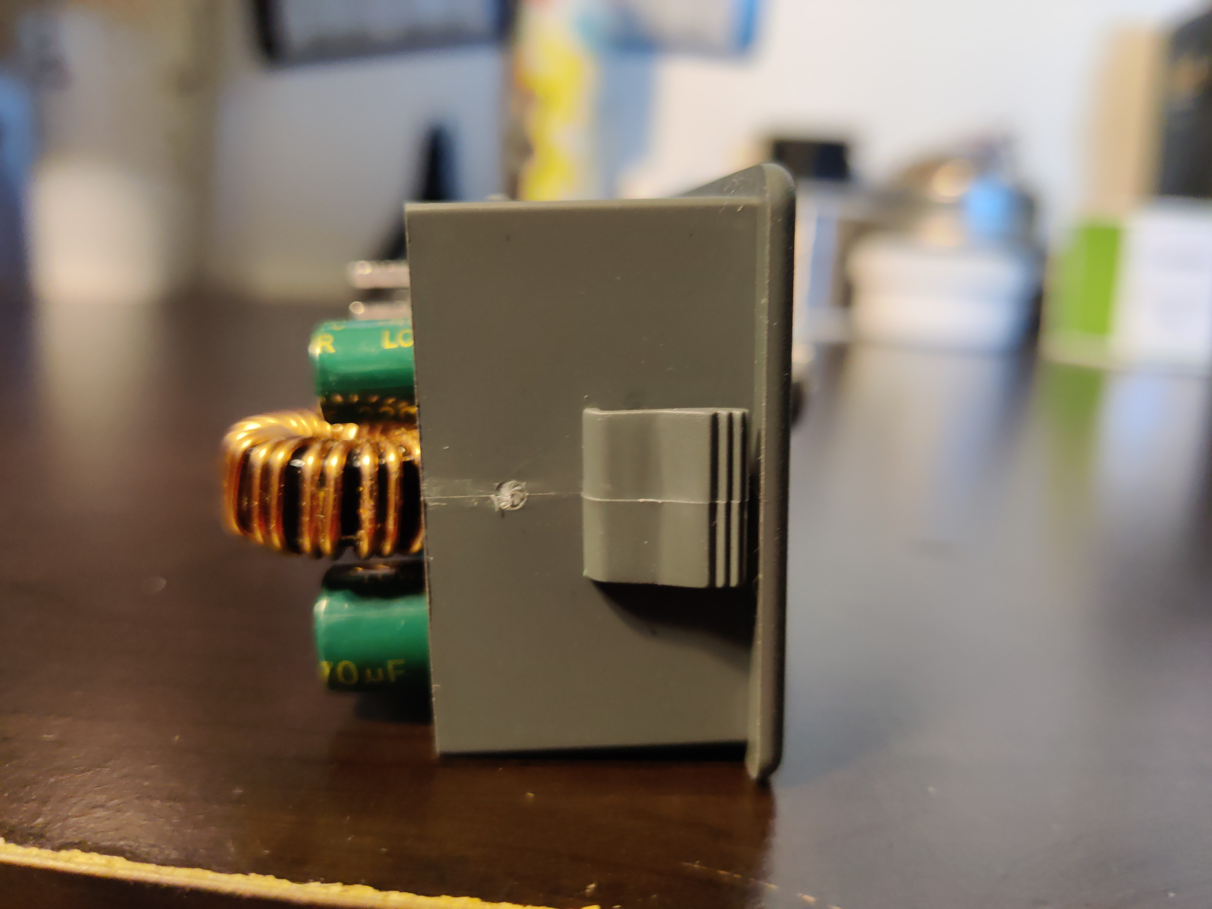
IMAGE 02
Top View - Controls
Two potentiometers for voltage and current adjustment. LED display provides real-time voltage readout.
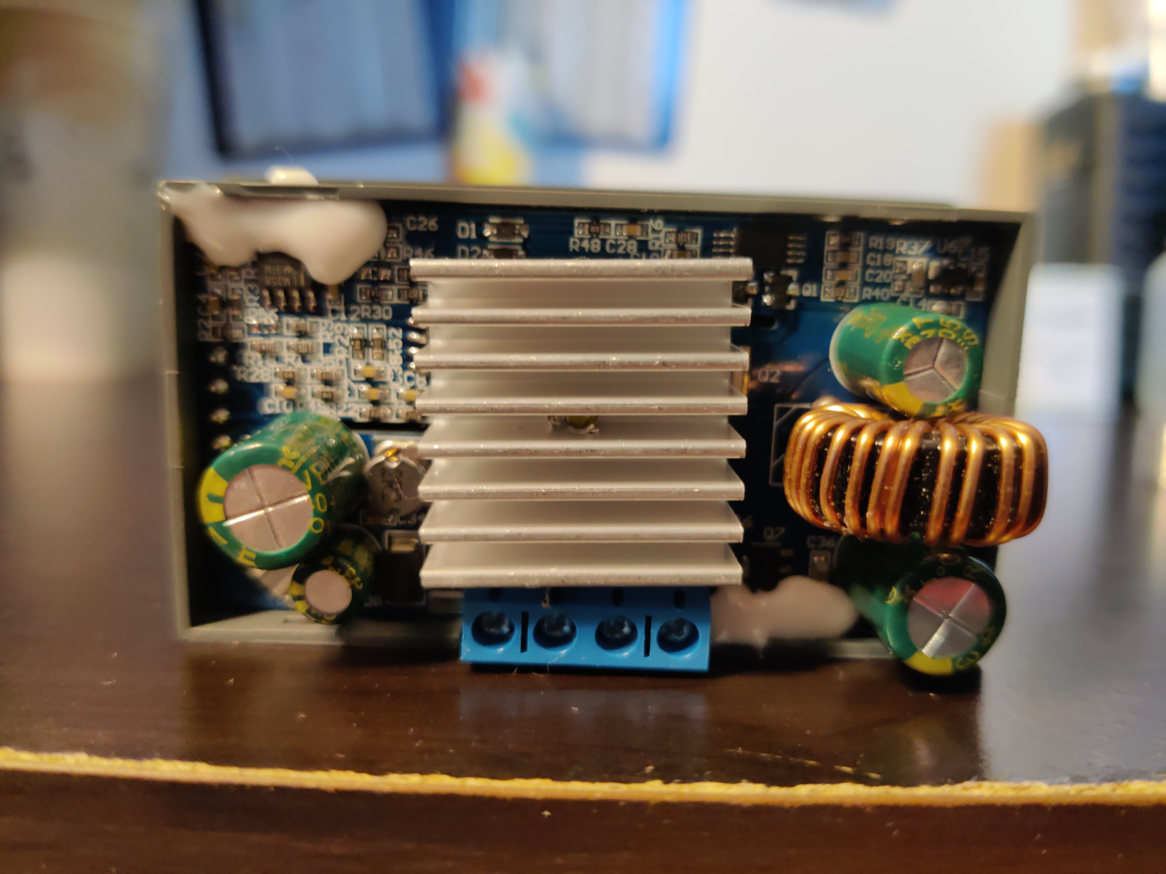
IMAGE 03
Bottom View - PCB
PCB layout reveals power trace routing. Wide copper pours handle 4A current without excessive I²R losses.
IMAGE 04
Power Inductor
Toroidal inductor (~100µH) with ferrite core. Critical component for storing energy in buck-boost switching cycle.
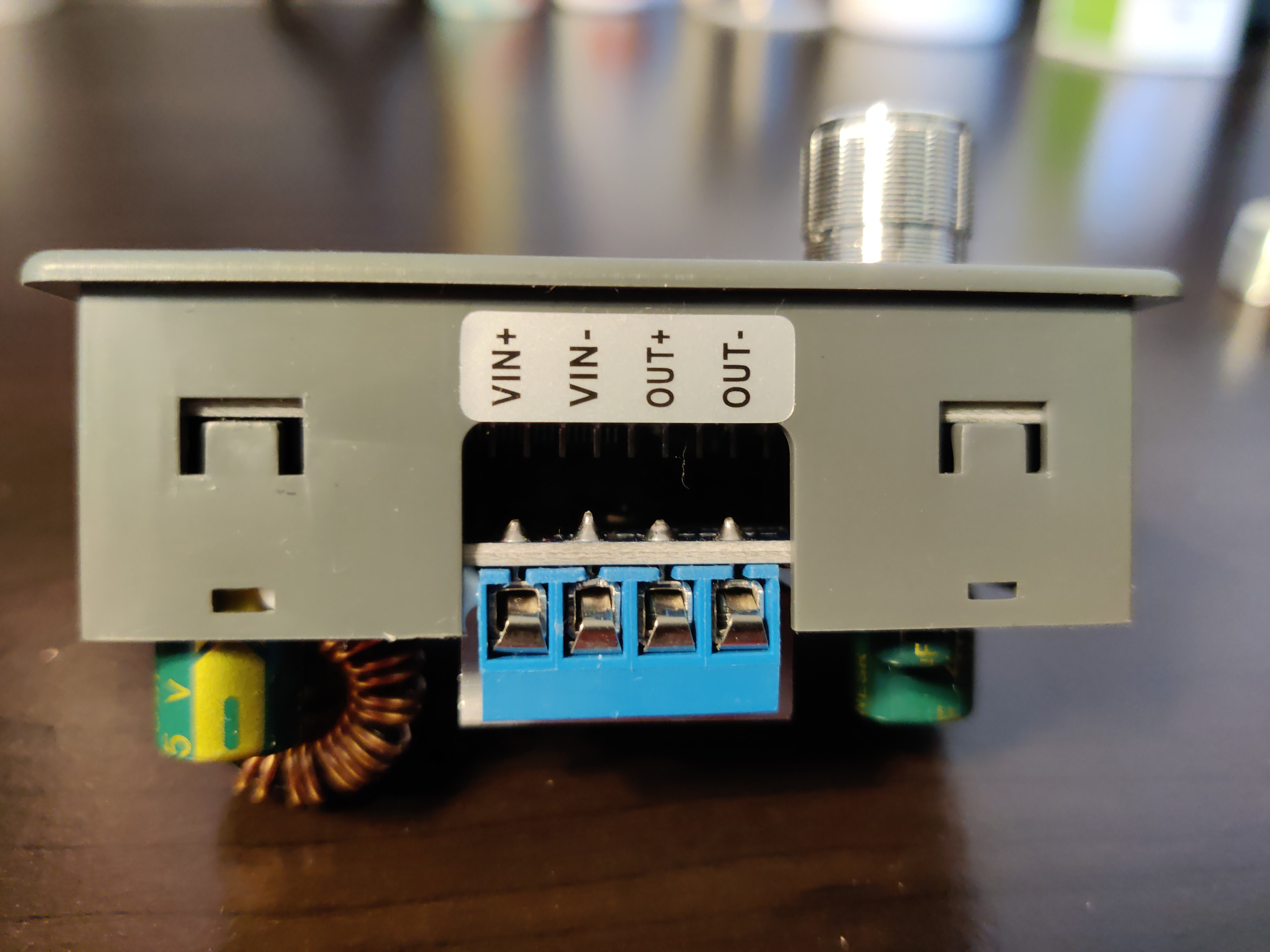
IMAGE 05
LED Display Driver
3-digit 7-segment LED with dedicated driver IC. Multiplexed display reduces pin count requirements.
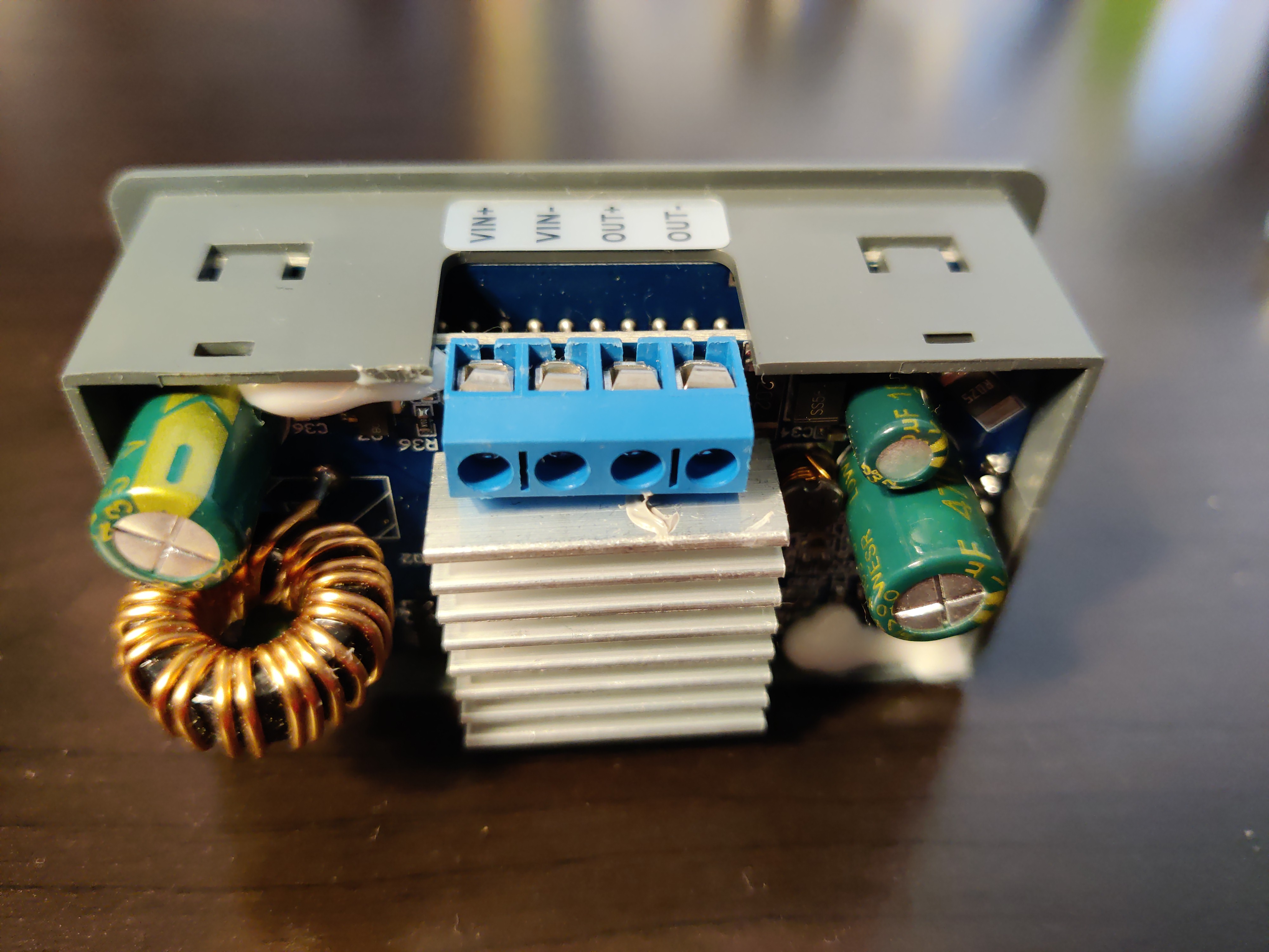
IMAGE 06
MOSFET Heatsinking
Aluminum heatsink bonded to switching MOSFET. Essential for thermal management at max 4A load.
×
‹
![]() ›
›