DC-DC Buck Boost Converter Analysis
Power Electronics Teardown: 0.5V-30V @ 4A
01. Project Overview
This project presents a comprehensive teardown and analysis of a commercial DC-DC buck-boost converter module capable of outputting 0.5V to 30V with a maximum current of 4A. Buck-boost converters are essential tools in any electronics lab, enabling efficient voltage regulation for prototyping, testing, and embedded system development.
Course: ECE 6723 - Electronics Dissection
Institution: Mississippi State University
Instructor: Faculty of Electrical & Computer Engineering
02. Project Documentation
The following table lists all project deliverables, including schematics, bill of materials, and analysis reports.
| Document Name | Description | Link |
|---|---|---|
| Project Description | ECE6723 - Electronics Dissection assignment details | View PDF |
| Project Proposal | Initial project scope and objectives | View Proposal |
| Display Schematics | Voltage display submodule circuit diagram | View PDF |
| Voltage Schematics | Buck-boost voltage regulation circuit | View PDF |
| Bill of Materials | Component list and pricing breakdown | View BOM |
03. Introduction
My name is Ajaya Dahal (AJ), and I was a senior Computer Engineering student at Mississippi State University at the time of this project (December 2022 graduation). This electronics dissection project was completed as part of ECE 6723, focusing on the practical analysis of commercial power electronics systems.
My academic interests span embedded systems design, communication systems, and computer vision with applications in autonomous vehicles (UAVs and UGVs). This project provided hands-on experience in power electronics design principles, including SMPS topology analysis, feedback loop stability, and component characterization.
Career Goal: Work as an embedded systems designer in the robotics/autonomy space, focusing on low-level hardware-software integration for real-time systems.
04. Project Proposal
The initial project proposal outlined the scope of work, target device specifications, and analysis methodology. The goal was to reverse-engineer a commercial buck-boost converter to understand its circuit topology, component selection, and efficiency optimization techniques.
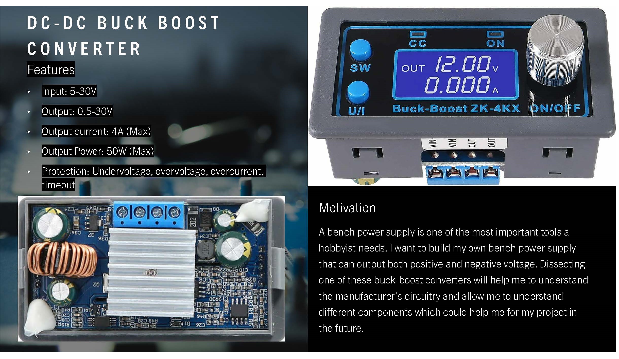
Figure 1: Original project proposal submitted for ECE 6723
05. Product Information
DC-DC buck-boost converter modules are indispensable tools in electronics laboratories. They enable prototyping and testing of circuits that require adjustable voltage rails, eliminating the need for multiple fixed-voltage power supplies.
Market & Retail Information
- Price: $12.54 (eBay, 2022)
- Manufacturer: ZK-4KX Electronics Parts
- Distributor: eBay marketplace
- Availability: Widely available from Chinese manufacturers
Technical Specifications
| Parameter | Value | Notes |
|---|---|---|
| Input Voltage | 5V-32V | Wide input range for versatility |
| Output Voltage | 0.5V-30V | Continuously adjustable via potentiometer |
| Output Current | 4A max | At optimal thermal conditions |
| Switching Frequency | ~100 kHz | Typical for this power class |
| Efficiency | Up to 96% | Varies with input/output voltage ratio |
| Topology | Buck-Boost (SEPIC) | Non-inverting, wide voltage range |
| Display | 3-digit LED | Real-time voltage readout |
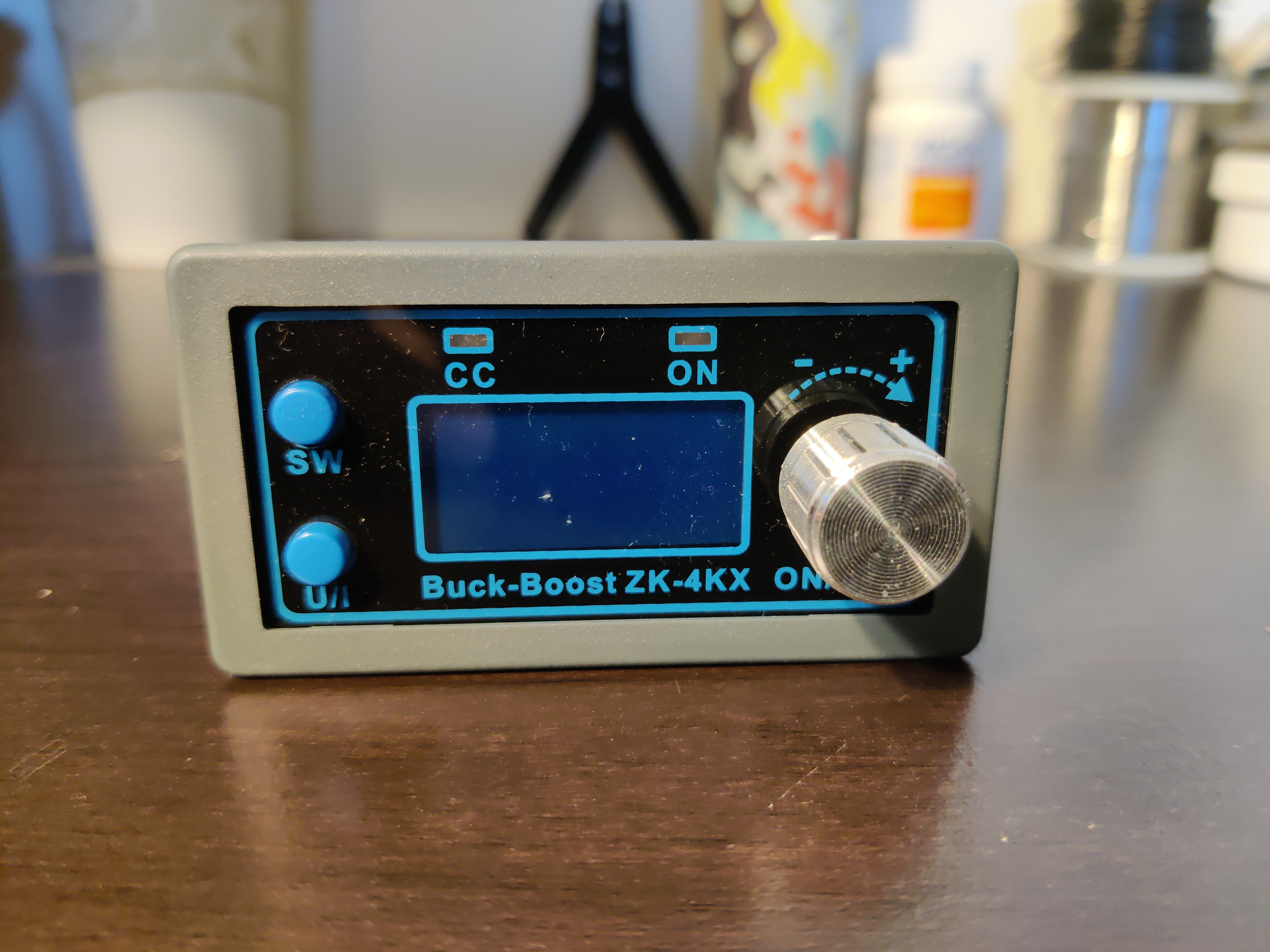
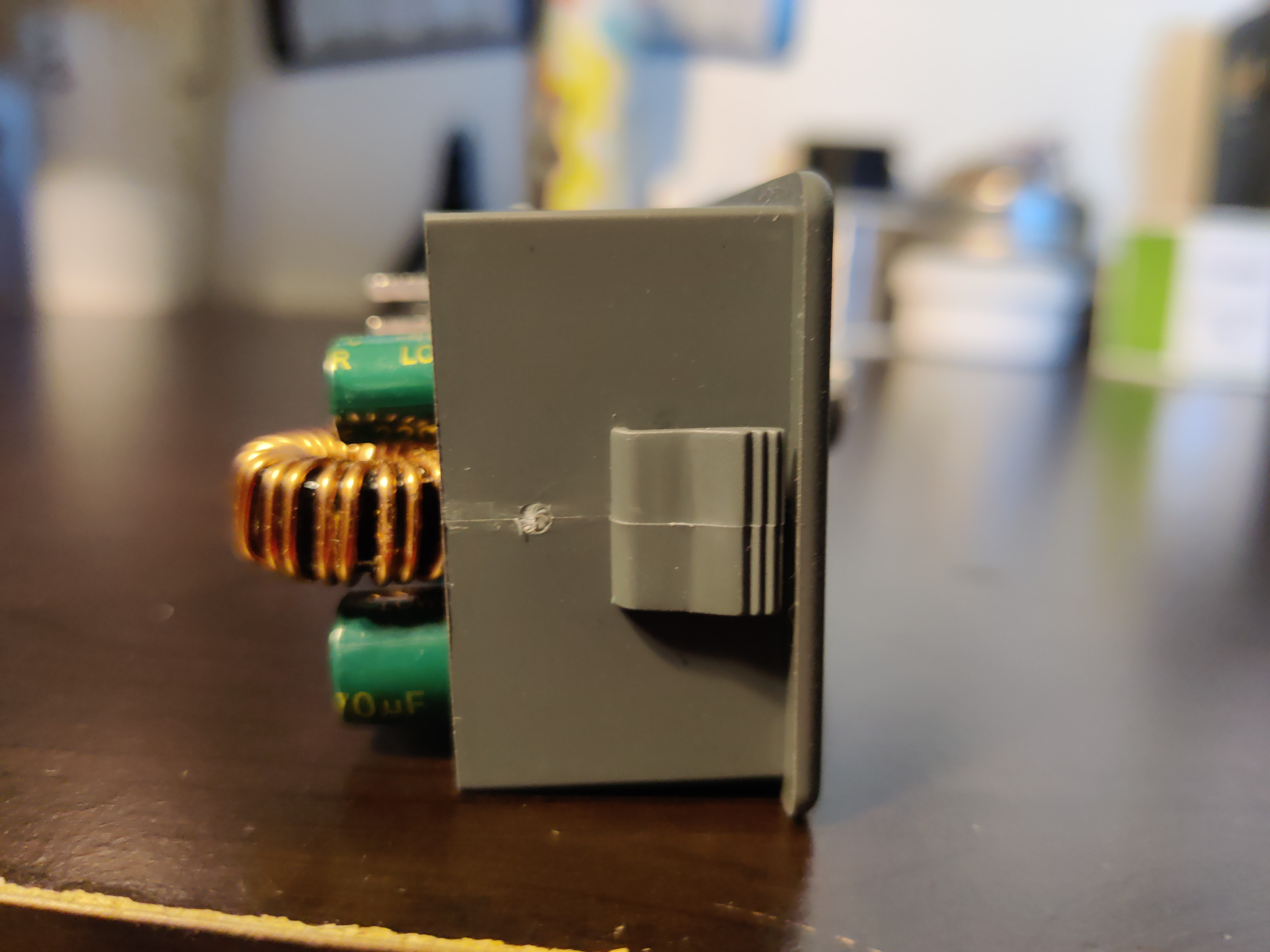
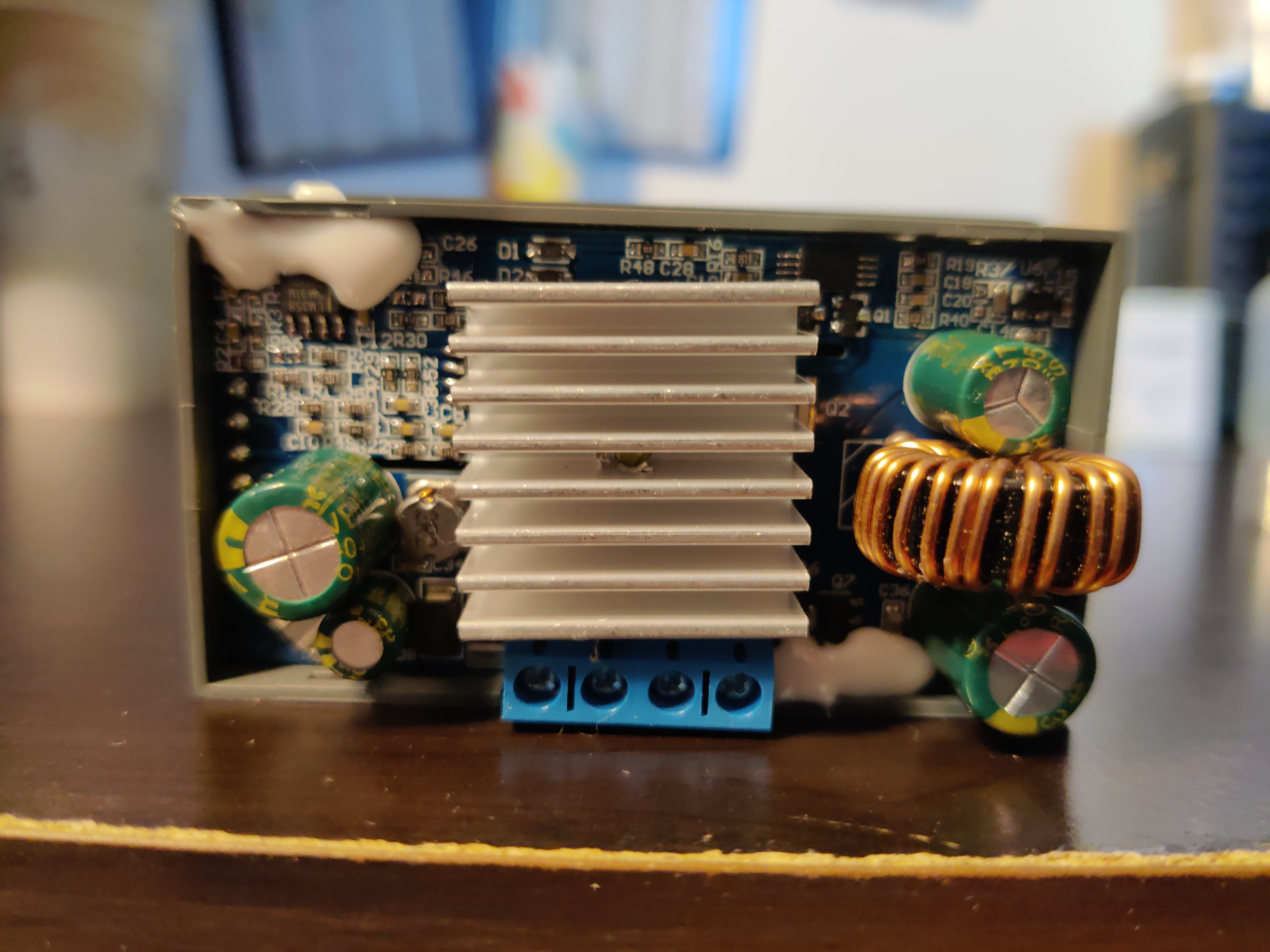
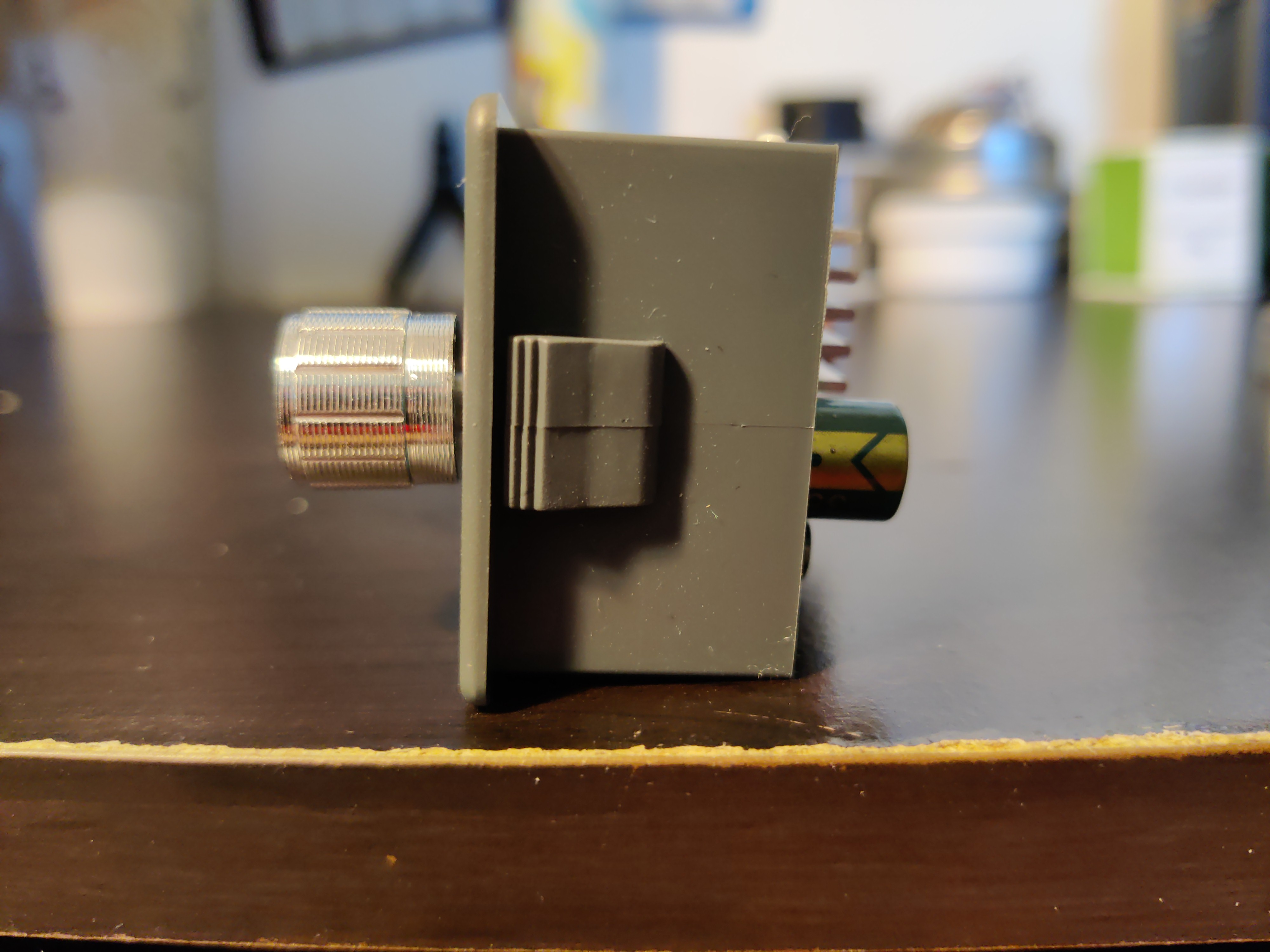
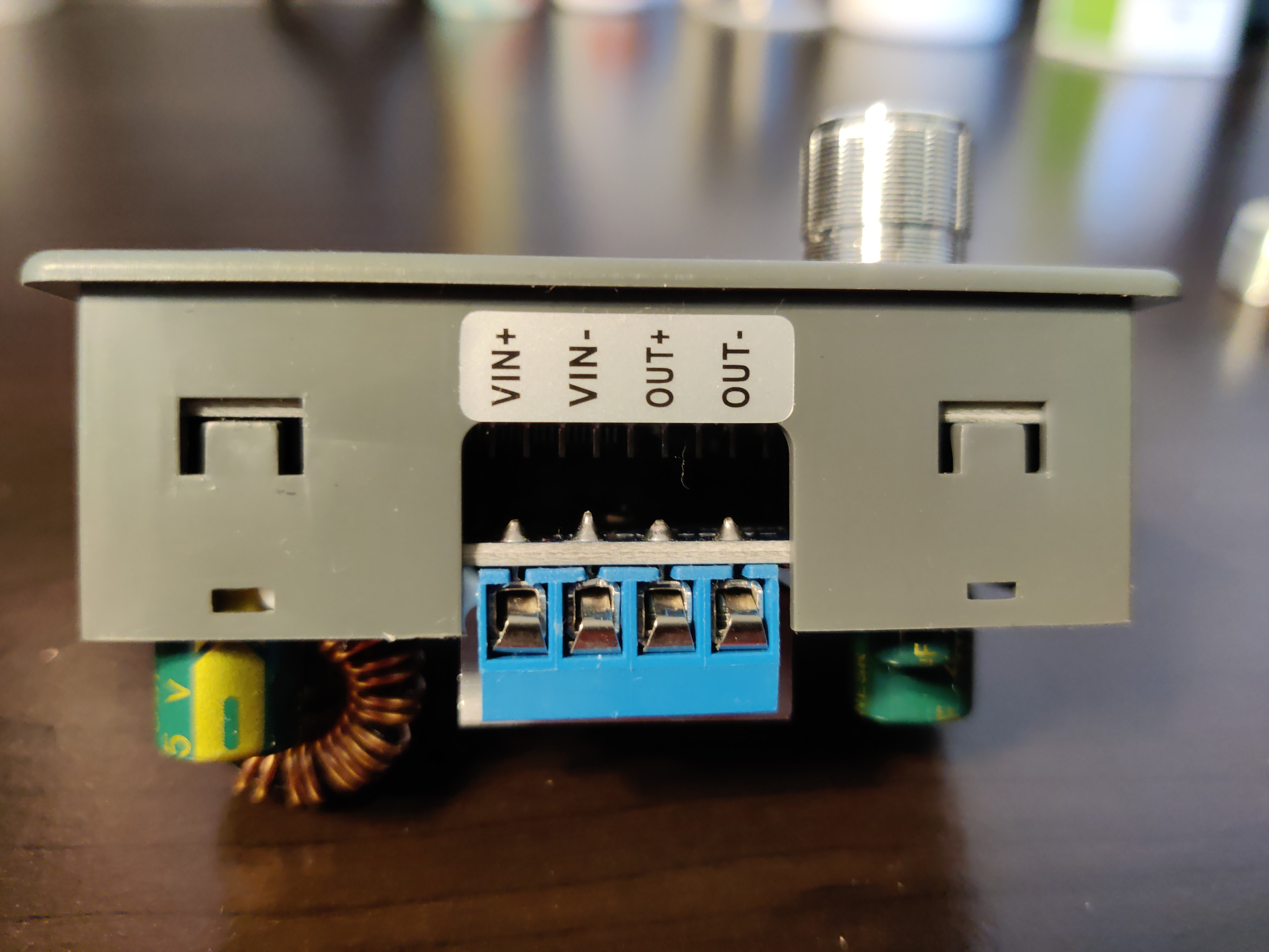
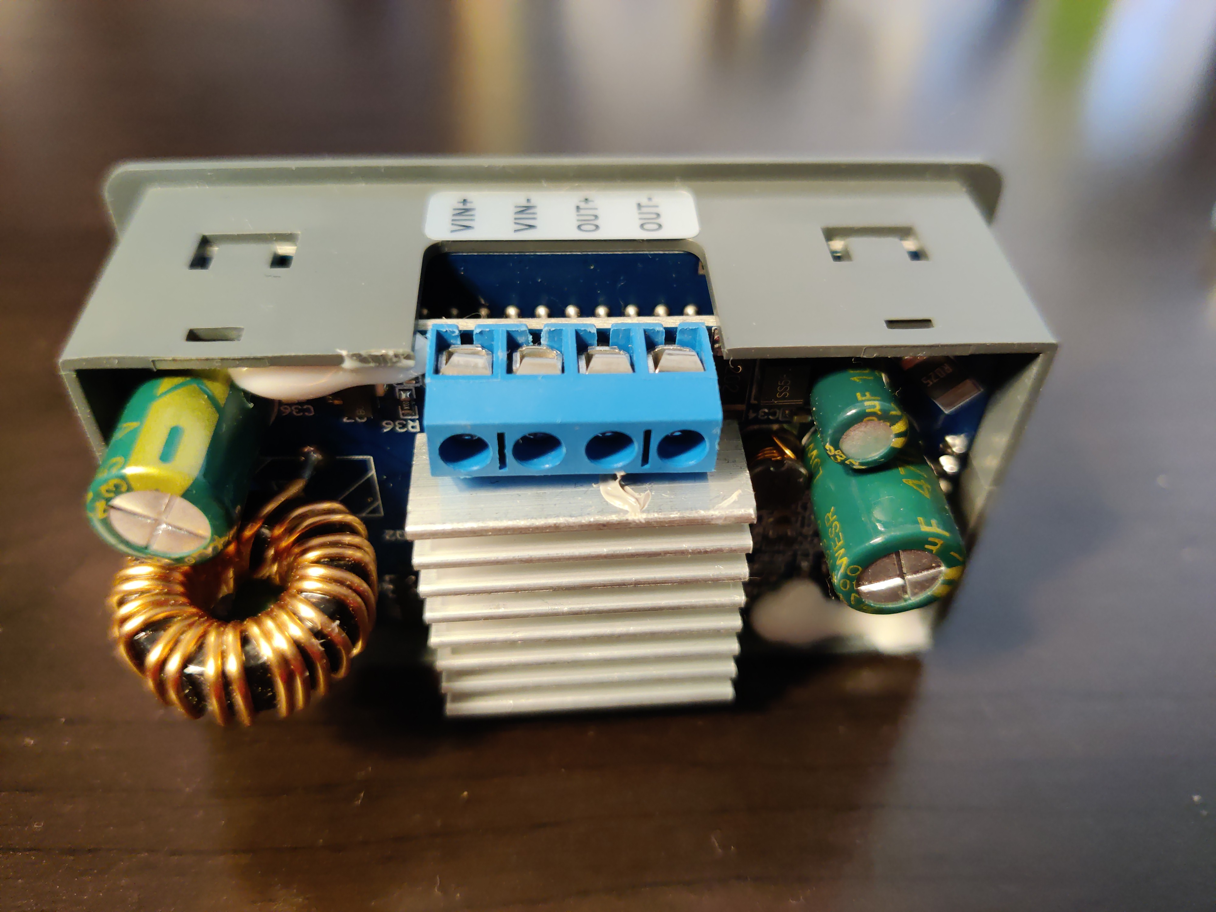
06. Photo Gallery
Detailed photographs of the teardown process, PCB analysis, and component identification. Click on any image to view the full interactive gallery.
Module in operation: voltage adjustment demonstration with real-time LED display feedback
View Full Gallery: Click here to access the interactive photo gallery →
07. Bill of Materials (BOM)
Approximate component costs based on market research and reverse-engineering of the PCB. Total BOM cost is significantly lower than retail price, indicating healthy profit margins for the manufacturer.
| Component | Specification | Quantity | Unit Cost | Total |
|---|---|---|---|---|
| PCB | 2-layer FR4, 60x40mm | 1 | $0.50 | $0.50 |
| Buck-Boost Controller IC | LM2596/XL6009 equivalent | 1 | $0.80 | $0.80 |
| Power Inductor | 100µH, 5A saturation | 1 | $0.40 | $0.40 |
| Schottky Diode | SS34, 40V 3A | 1 | $0.15 | $0.15 |
| Electrolytic Capacitors | 220µF-470µF, 35V | 3 | $0.20 | $0.60 |
| LED Display Module | 0.36" 3-digit, 7-segment | 1 | $0.60 | $0.60 |
| Potentiometers | 10kΩ multi-turn trimpot | 2 | $0.25 | $0.50 |
| Resistors & Misc | Assorted SMD/THT | ~20 | $0.20 | $0.20 |
| Total BOM Cost (Est.) | $3.75 | |||
Profit Margin Analysis: Retail price $12.54 vs. BOM cost $3.75 = ~70% gross margin. This accounts for manufacturing, assembly, testing, logistics, and distributor margins. Typical for consumer electronics.
08. Key Takeaways
This project provided hands-on experience in power electronics reverse-engineering and circuit analysis. Key learnings include:
- Buck-Boost Topology: Understanding of SEPIC/Ćuk converter variants for wide input/output voltage ranges
- Feedback Loop Design: Analysis of voltage regulation, load regulation, and transient response
- Component Selection: Trade-offs between inductor saturation current, ESR, and ripple current
- Thermal Management: Heatsinking requirements for MOSFETs and diodes at max load
- Cost Optimization: Chinese manufacturers achieve excellent price/performance through volume and vertical integration
Final Grade: Successfully completed all project requirements including reverse-engineering, schematic capture, BOM analysis, and technical presentation.