Buck boost converter that is capable
of outputing 0.5V to 30V with max
current of 4A.
| Document Name | Description | Download |
|---|---|---|
| Project Description | ECE6723 - Electronics Dissection assignment details |
Assignment_Details.pdf |
| Project Proposal | Initial idea of the project |
Proposal |
| Schematics | Schematics of the board | |
| BOM | Bill of Materials - Price of parts |
BOM |
My name is
Ajaya Dahal - AJ , senior student majoring in computer engineering as Mississippi State University. I am graduating in the December with Bachelors of Science in Computer Engineering.
I want to pursue a master's after my graduation. After my master's degree, I want to work as an embedded system designer for a few years before coming back for Ph.D. I am interested in communication and computer vision that has direct
application in UAVs and UGVs. This webpage is designed for ECE 6723, reporting the dissection of an embedded system. The following sections explain the process starting with proposal.
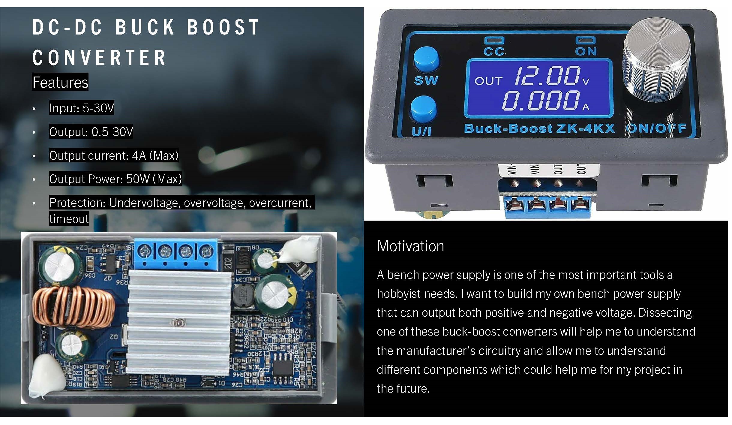
DC-DC buck-boost converter modules are a must-have tools in any lab. It comes very handy in the lab while prototyping, building, and experimenting with any electronic design.
The price and manufacture information is listed below:
The following table presents the features this device has:
| Features | Range |
|---|---|
| Input Voltage Range | 5-30V |
| Output Voltage Range | 0.5 - 30V |
| Output Current | 4A (Max) |
| Output Power | 50W (Max) |
| Protection: | Under-voltage |
| Over-voltage | |
| Over-current | |
| Time-out | |
| Soft start | Yes |
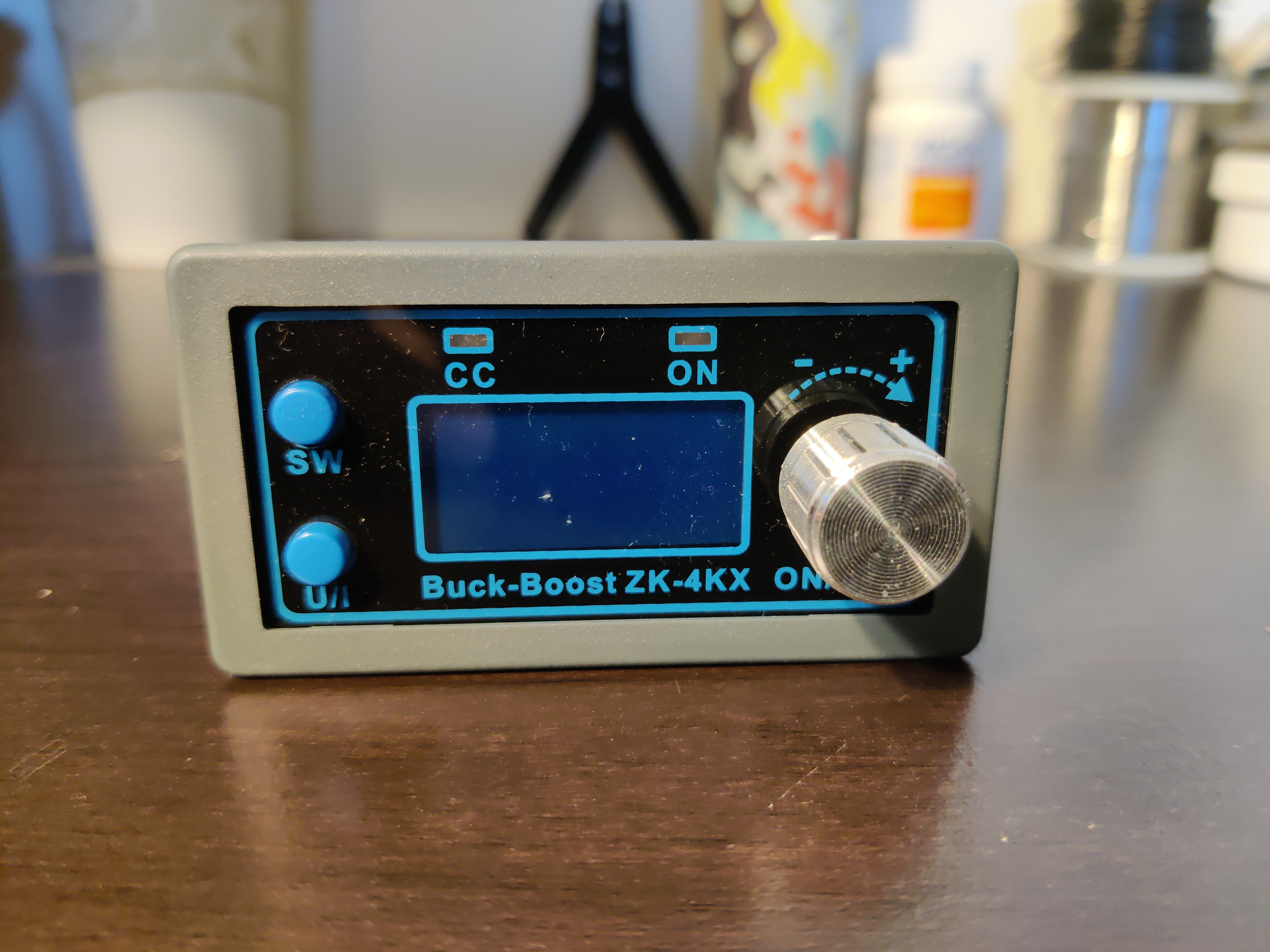
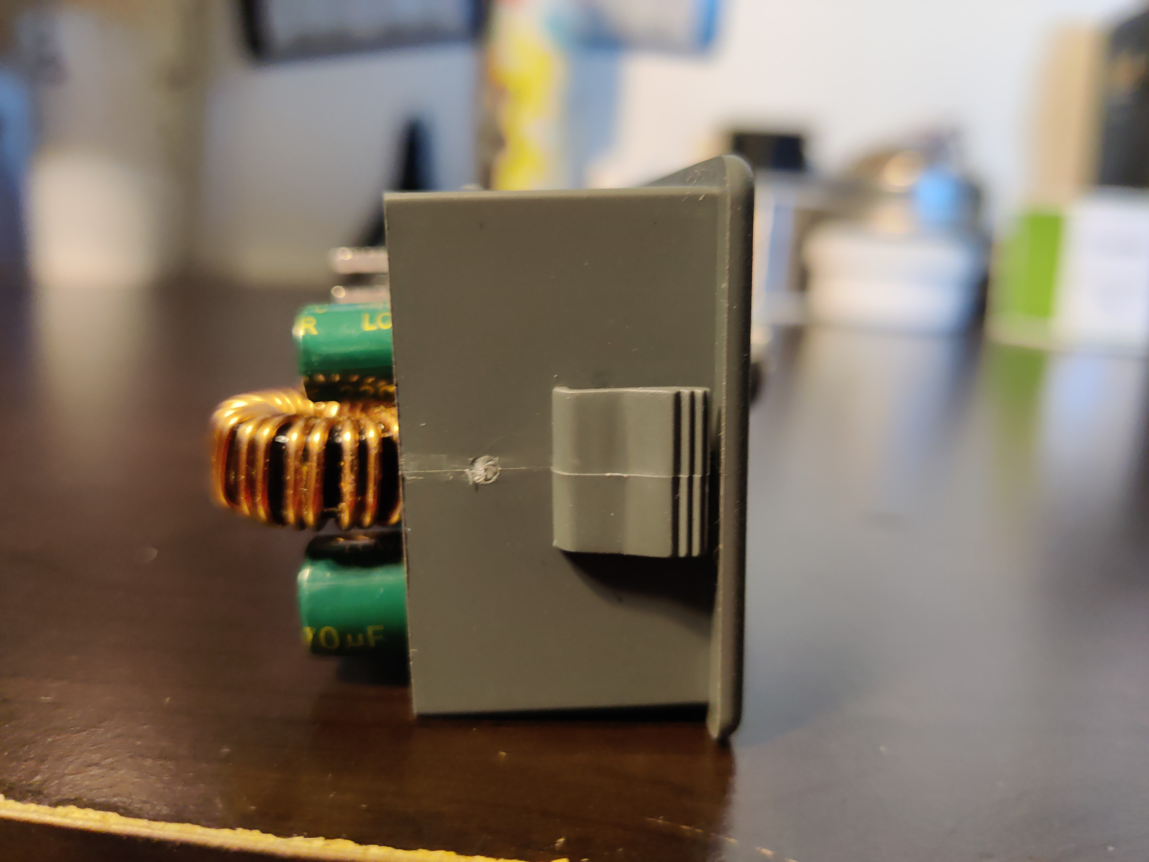
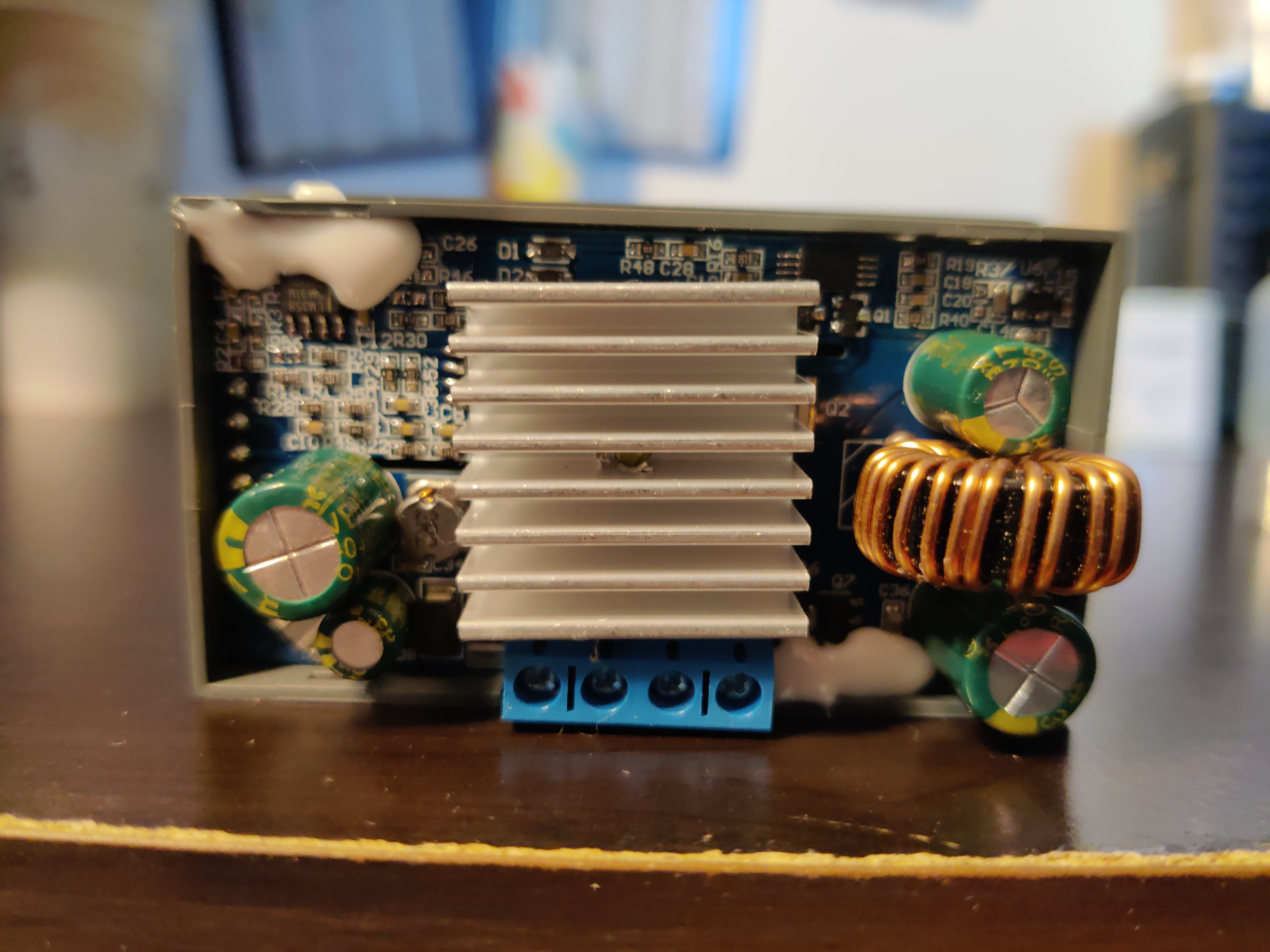
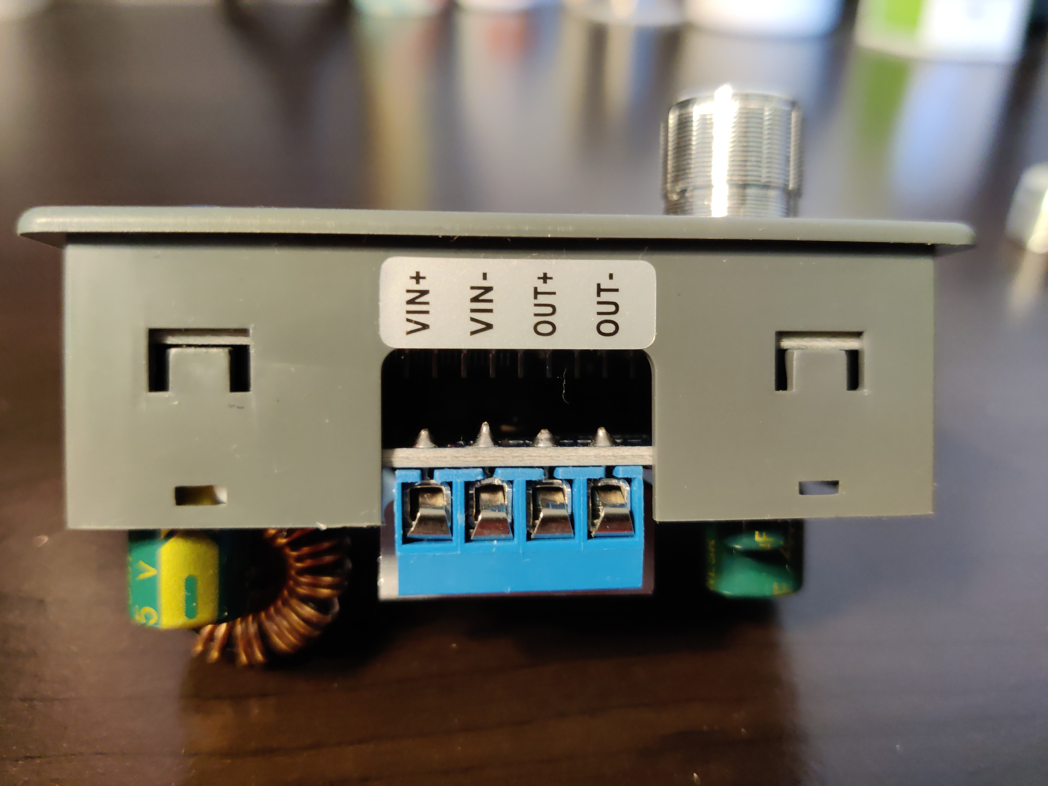
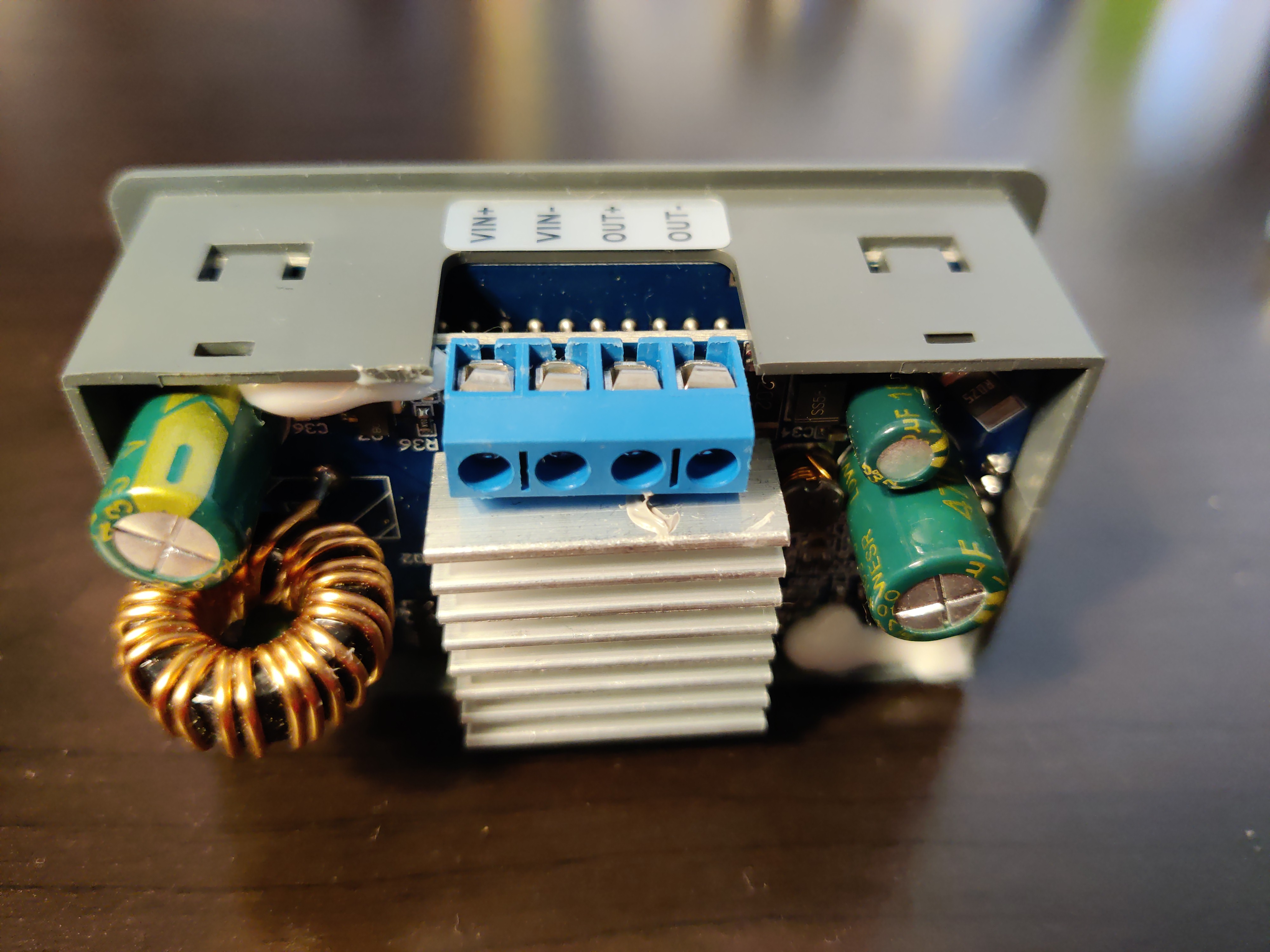
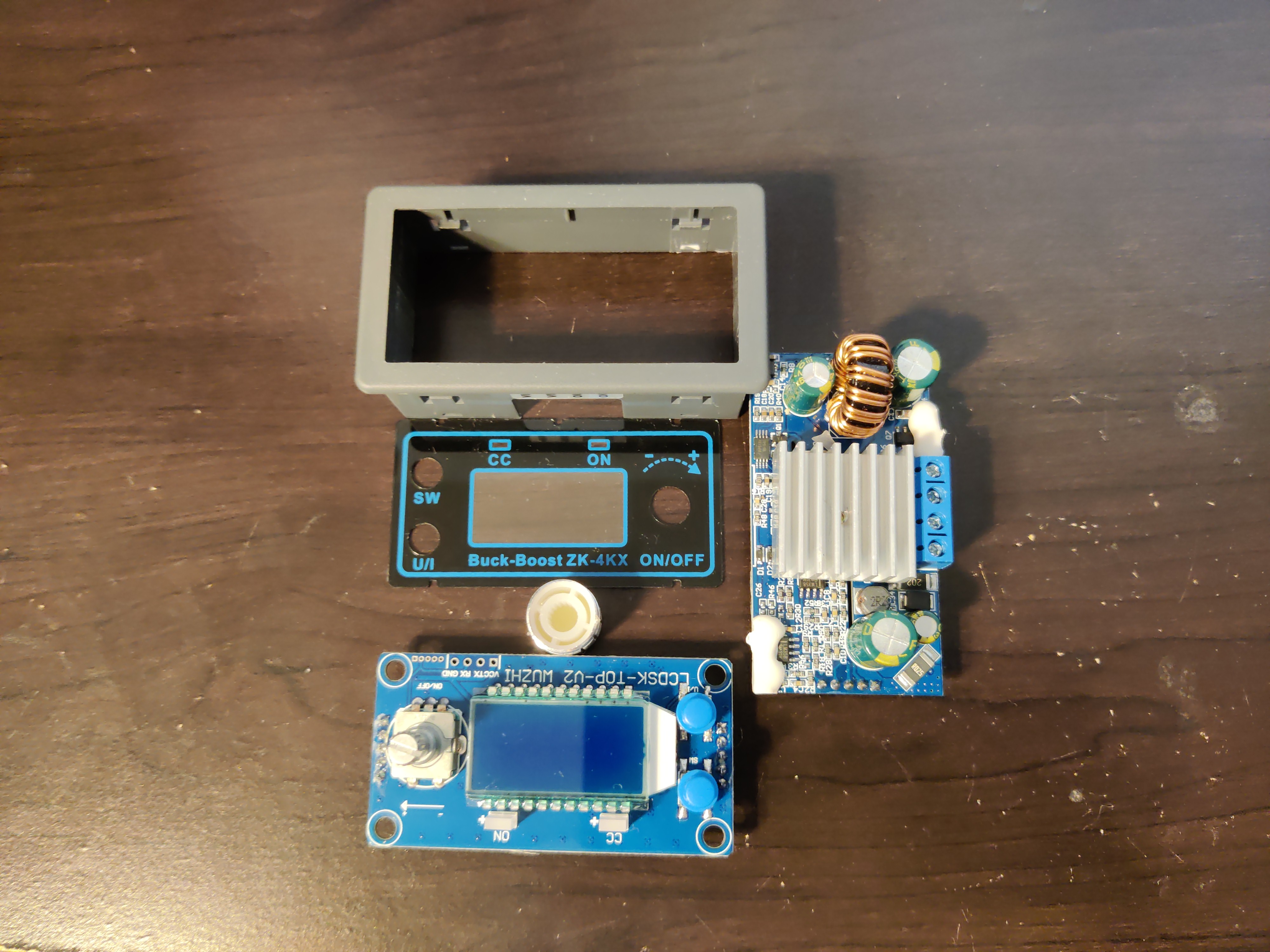
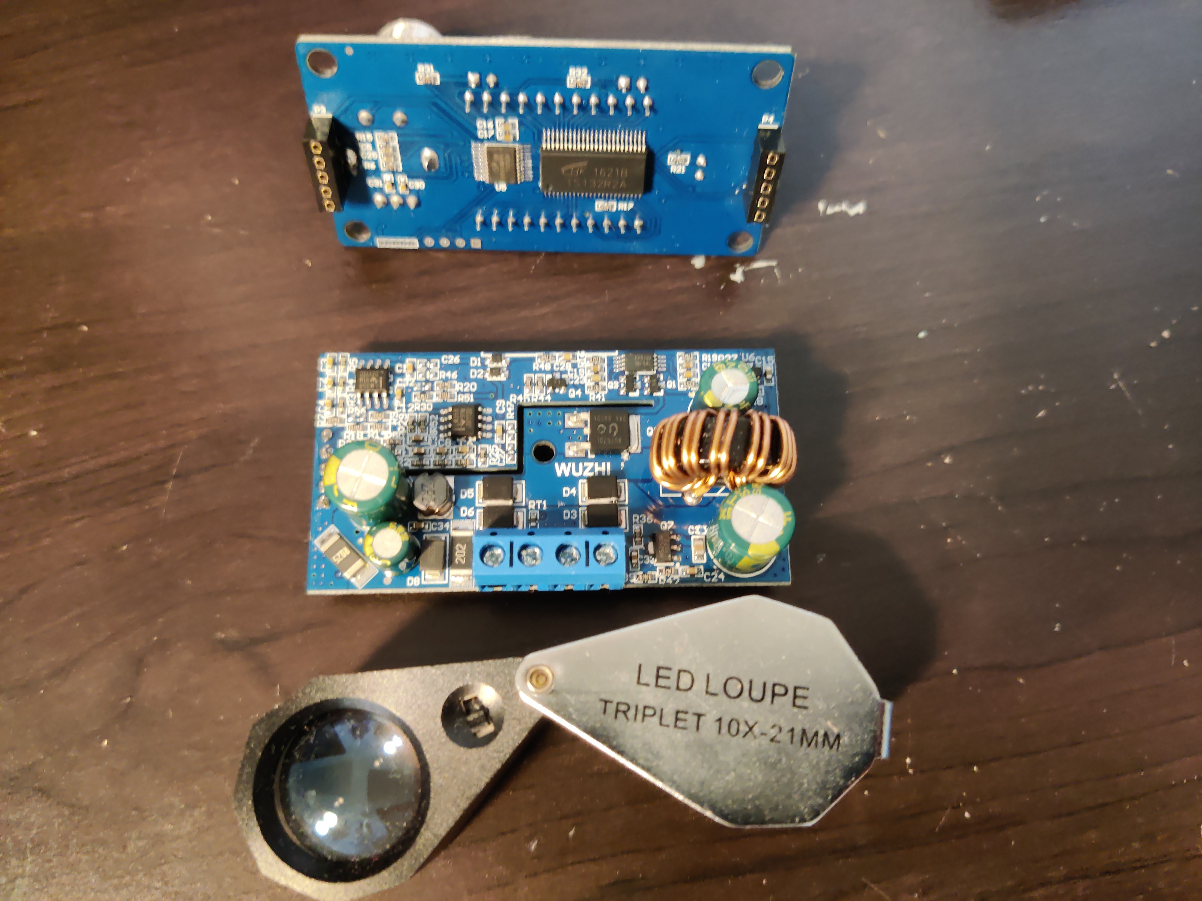
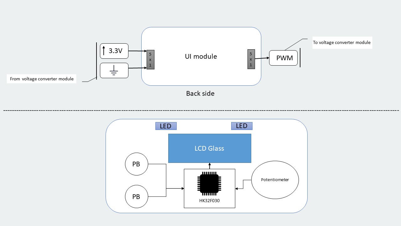
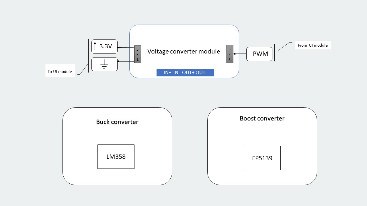
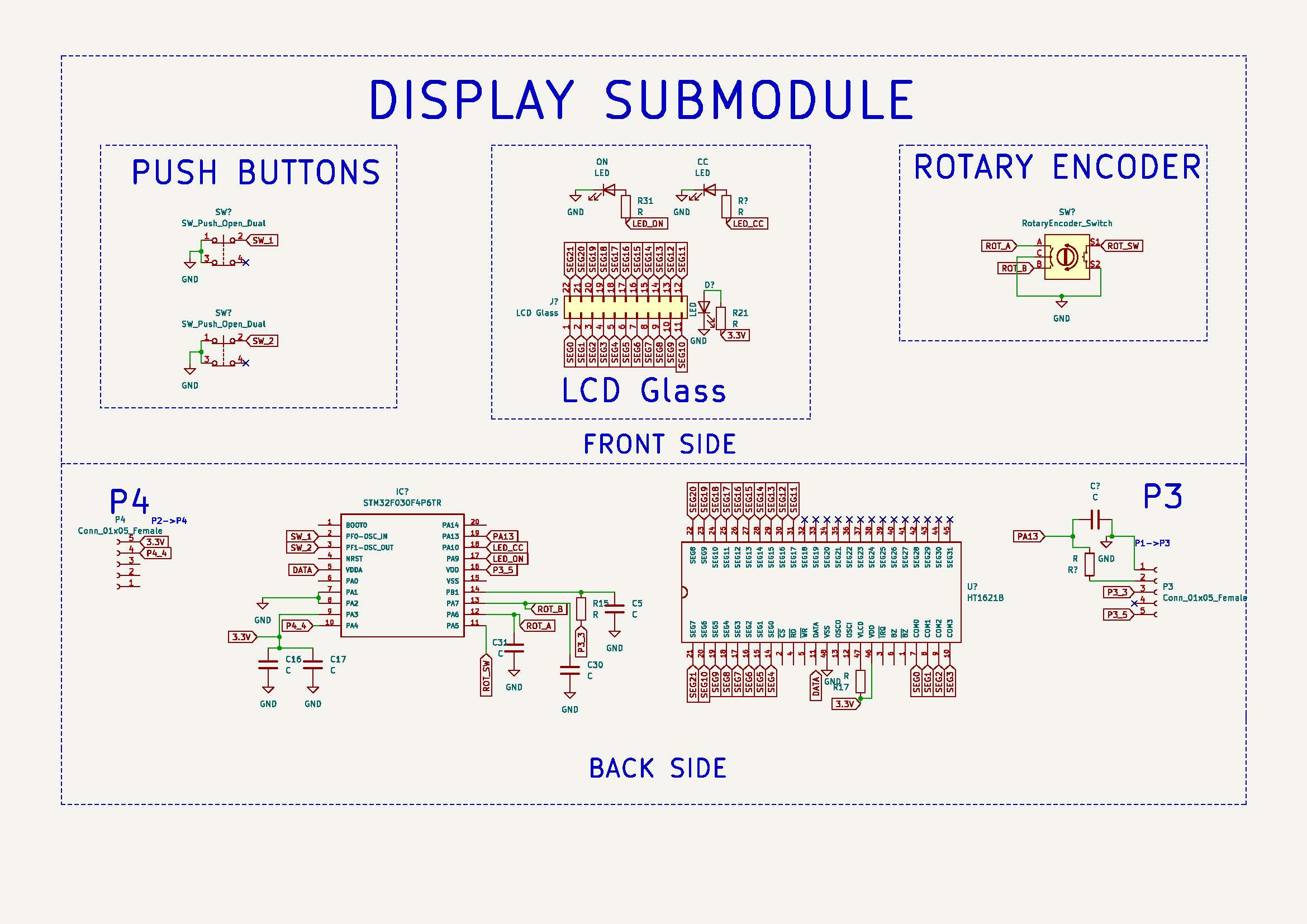
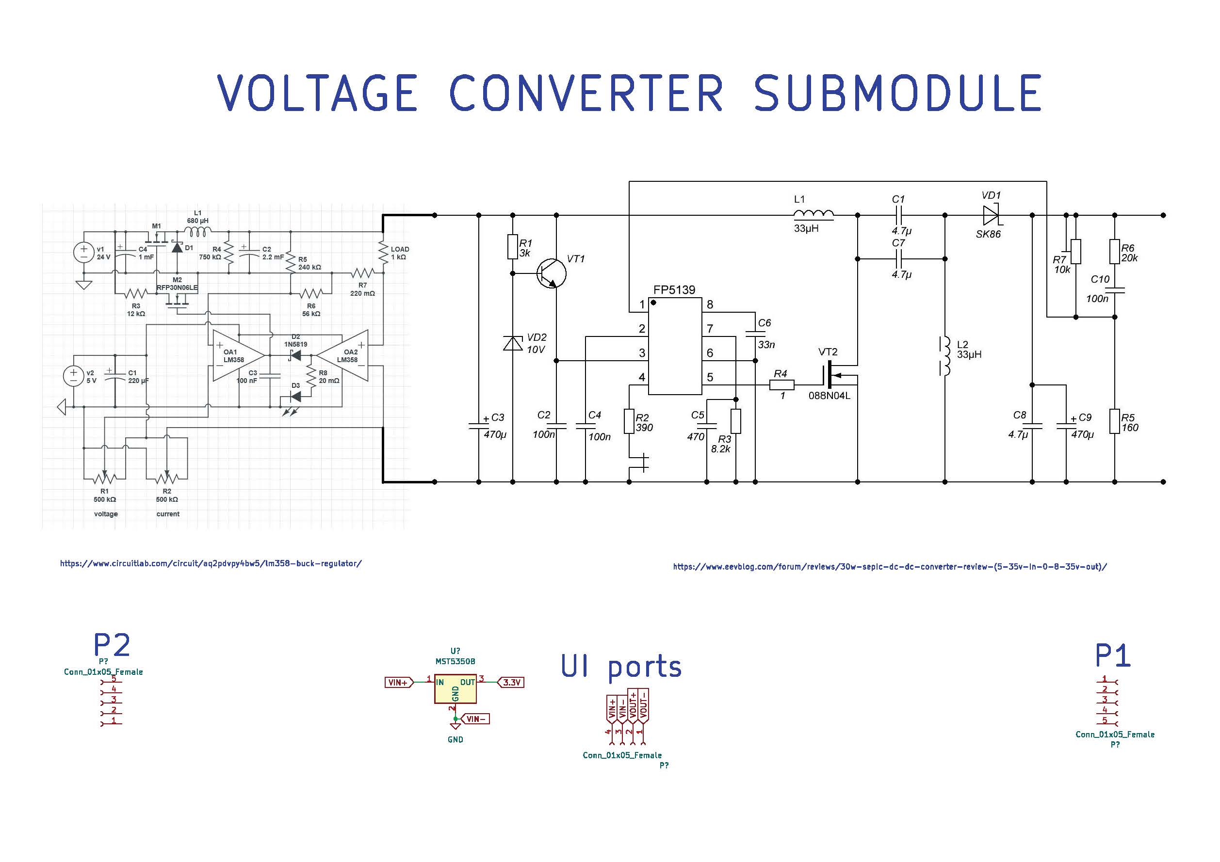
The dissection began by observing the product. After that the device is taken apart it is found that the buck-boost converter module has two submodules which is referred to LCD module (or sometime referred as UI module or Display module) and voltage converter module.
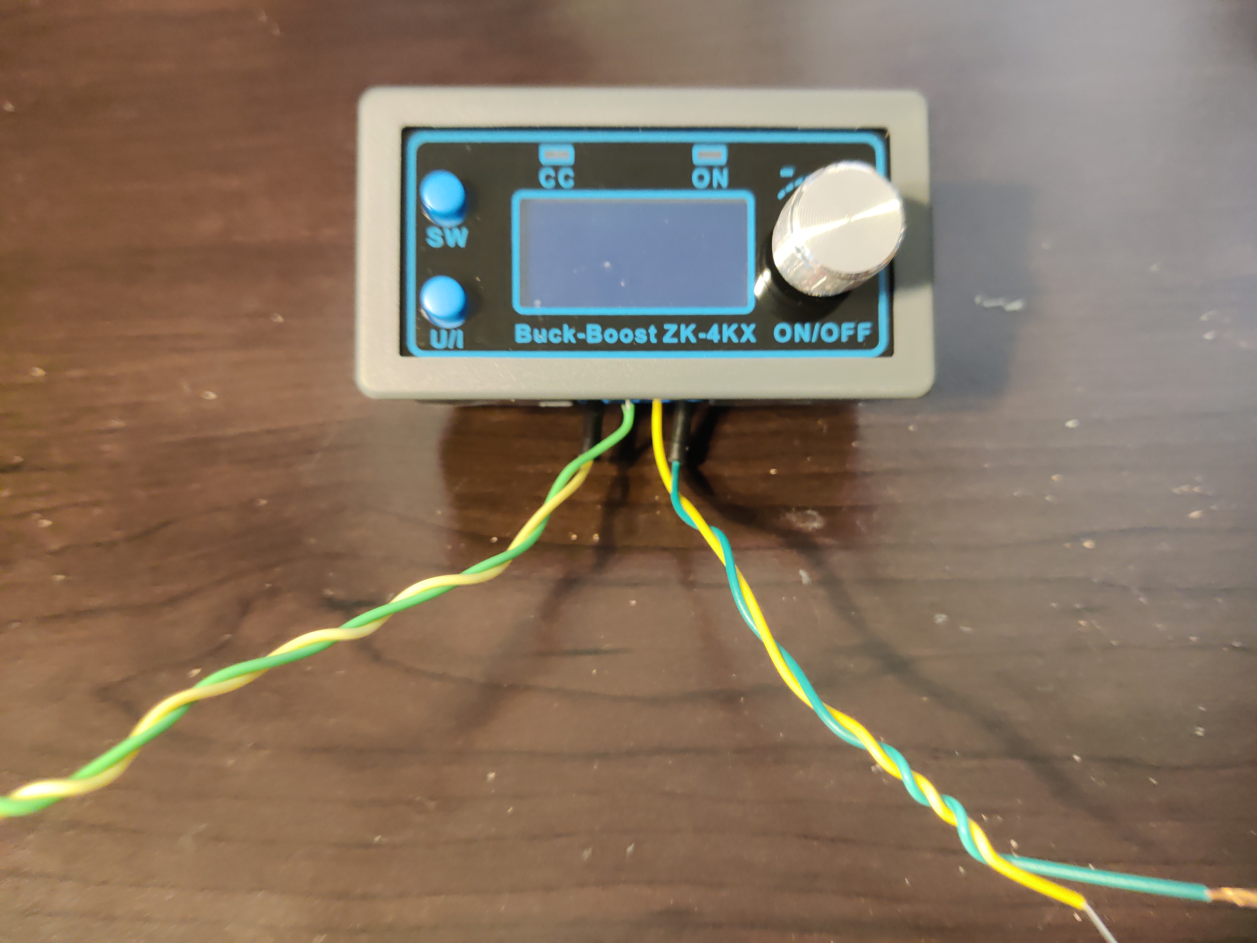
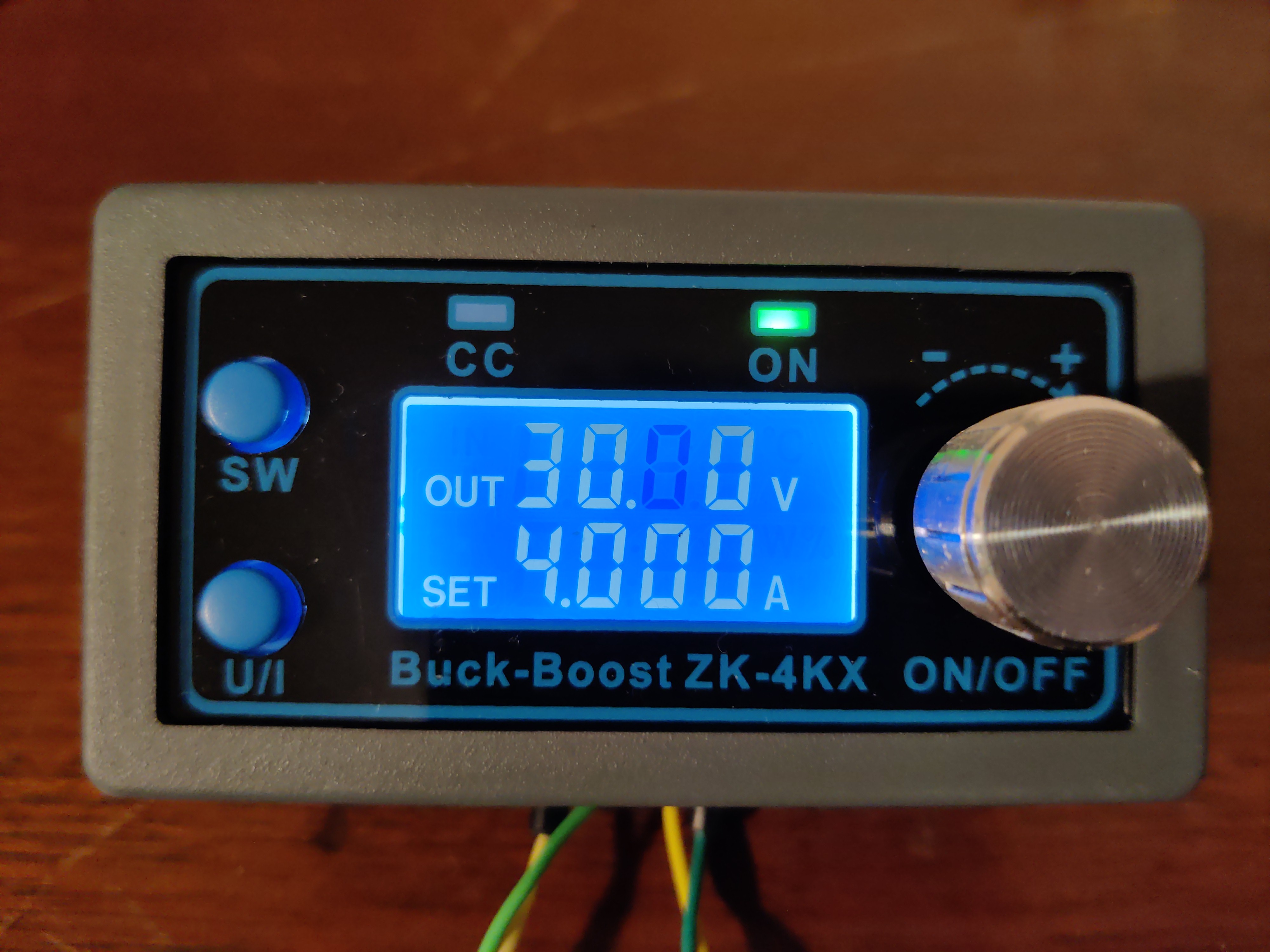
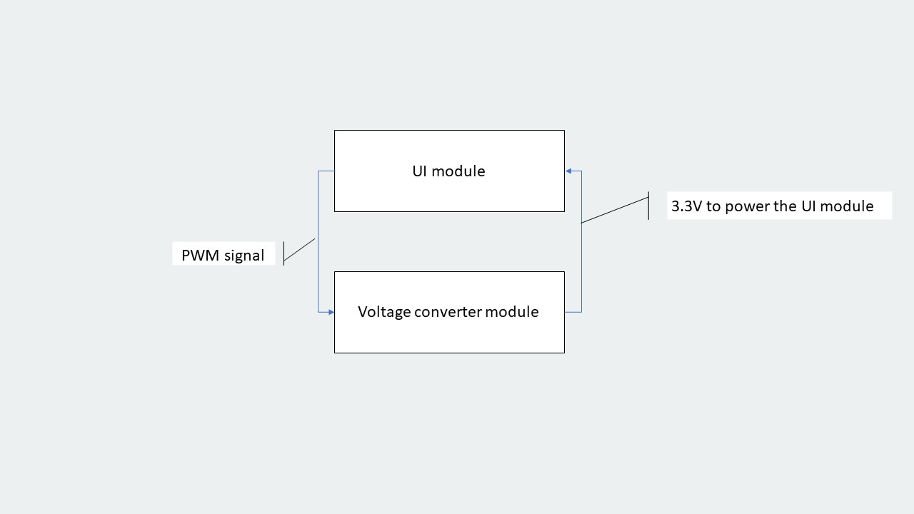
As mentioned above, the LCD module has UI inputs and outputs. Based on the user's selection to obtained the desired voltage, they can use rotory encoder, and the microcontroller generates variable PWM signal which is fed to the other module;
voltage converter module that then generates the requested voltage. The other two buttons SW and U/I are used to set different parameters as shown below:
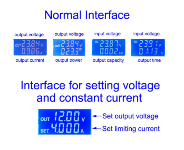
The information presented below about the UI option has been verified first and obtained from the user manual:
“Switch display parameters -- in the normal interface, press SW to switch the display below the display screen, and switch
the display content between current A power W capacity Ah time h. Long press SW button to switch the uplink display on the display screen and switch the display content between input voltage IN output voltage OUT.
Set output
voltage -- press U/I button in the normal interface to enter the interface of setting voltage constant current. It can be seen that a certain digit of the output voltage value is flashing. Rotate the encoder left and right to adjust
the major and minor. Short press the rotary encoder to choose which bit of output voltage to set. After setting, press U/I button 2 times to return to the normal interface. Or automatically return to the normal interface after stopping
operation for 10s.
Set constant current value (that is, the maximum current value allowed to output by the module) -- press U/I button in the normal interface to enter the setting voltage constant current interface. Then press
U/I button and switch to setting constant current value. You can see a bit of the setting constant current value flashing. Rotate the rotary encoder left and right to adjust the major and minor. Short press the rotary encoder to choose
which bit to set the constant current value. After setting, press U/I to exit the setting voltage constant current interface and return to the normal interface. Or automatically return to the normal interface after stopping operation
for 10s.
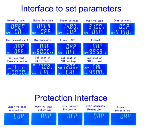
Set the default on/off state of module power-on -- long press U/I in the normal interface to enter the parameter setting interface. You can see that it shows "OPEN OFF" or "OPEN ON". "OPEN OFF" means the output is
turned OFF by default when power is ON, and "OPEN ON" means the output is turned ON by default when power is ON. Long press rotate encoder to switch two states. After setting, long press U/I to return to the normal interface.
Setting of protection parameters on state and threshold -- long press U/I to enter the parameter setting interface in the normal interface. Press SW until the protection you want appears. UP -- undervoltage protection threshold; OUP
-- overvoltage protection threshold; OCP -- overcurrent protection threshold; OAP -- ultra-capacity protection threshold; OHP timeout protection threshold. Short press rotate encoder to select which bit you want to set the protection
parameter. Long press the rotary encoder to set the protection parameters on or off (only timeout protection and super capacity protection can be set to turn on/off, and other protection parameters are turned on by default.).Rotate
the encoder left and right to make the parameters bigger and smaller. After setting, long press U/I to return to the normal interface.
Calibration voltage and current -- press U/I button to enter the parameter setting interface
under normal interface. Press SW key for a short time until the interface with zero appears, with zero + out + a symbol. Press and hold the rotary encoder to complete zero calibration. Short press SW button until a parameter interface
with CAL appears. The calibration input voltage interface with the symbol CAL+IN+V; The calibration output voltage interface with the symbol CAL+OUT+V; The calibration output current interface with the symbol CAL+OUT+A. Rotate the
encoder left and right to adjust the size of parameters. After the adjustment is completed, long press the rotary encoder to confirm the adjustment is completed, and the parameter value is no longer flashing. Long press U/I to return
to the normal interface.”
General Overview
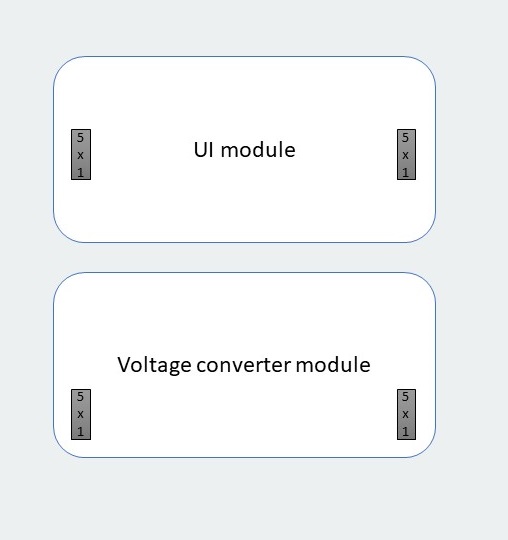
Input and output of each submodules
Detail Input and Output of submodules
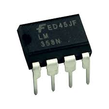
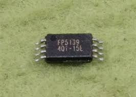
There are two major IC that is used to "boost" and "buck" the voltage. LM358 is used to buck the voltage by implementing negative gain whereas for "boosting" the voltage, FP5139 dedicated boost converter IC is used. One of the twos LM358 opamp compares the input voltage with the requested voltage and selects the output from one of these circuits to output the user-desired voltage.
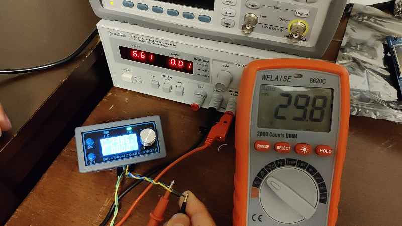
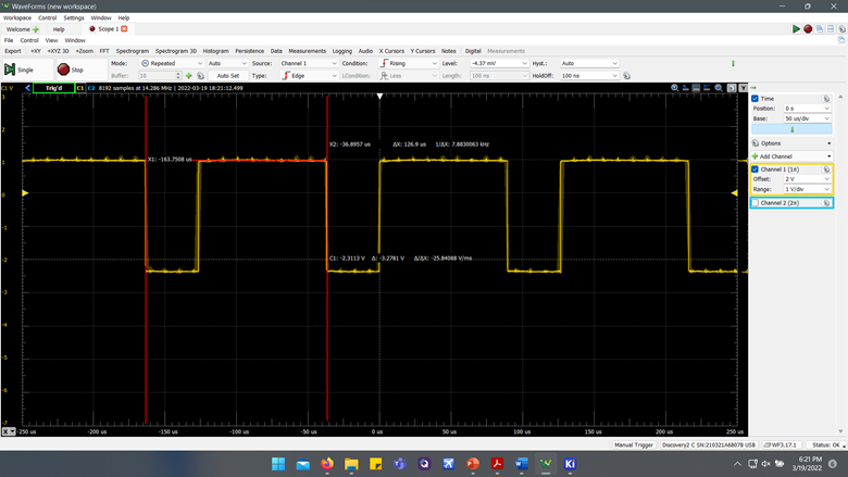
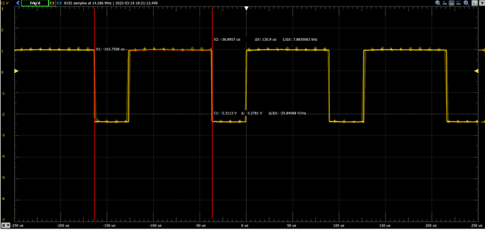
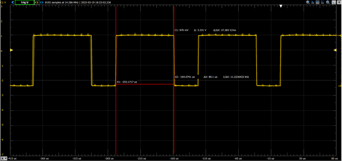
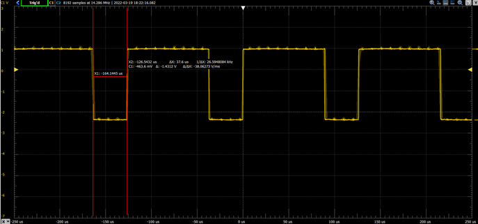
The PWM generated by the LCD module is obtained by probing NI analog discovery portable oscilloscope and the results are presented below:
(Click to enlarge)
From this dissection, I learned the working mechanism of the buck-boost converter. One may replicate this module using the information below. First, all the components used in these modules were studied. Below is the table that shows all the major components in detail:
| Name of the component | Quantity | Description | Image | Datasheet | Price/Link |
|---|---|---|---|---|---|
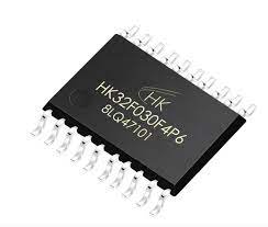
| HK32F030F4P6 | 1 |
|
 |
$0.7232 |
|
| HT1621 | 1 |
|
 |
HT1621.pdf |
$0.3264 |
| LM358 | 2 |
|
 |
LM358.pdf |
$0.16759 |
| FP5139 | 1 |
|
 |
FP5139.pdf |
$0.3571 |
| SS8050 | 2 | NPN transistor with 1.5A collector current. | 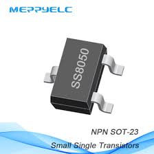 |
SS8050.pdf |
$0.0075 |
| SS56 | 1 |
|
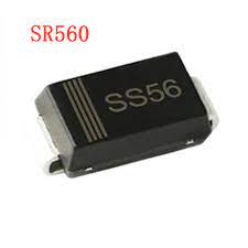 |
SS56.pdf |
$0.0446 |
| SS8550 | 2 | PNP transistor with -1.5A collector current. | 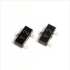 |
SS8550.pdf |
$0.0095 x 2 = 0.019 |
| Special Resistors: R025, R202 | 1 each | 0.0250 Ohm and 2K Ohm reistors in SMT formfactor. | 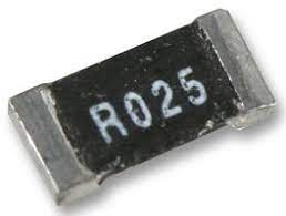 |
||
| ME6209 | 1 |
|
 |
ME6209.pdf |
$0.0521 |
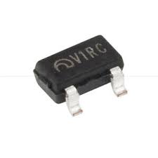
| RU7570L | 1 | 75V 70A N Channel Power MOSFET | 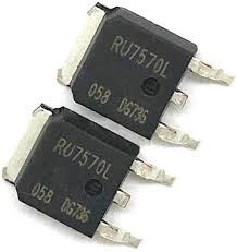 |
RU7570L-Ruichips.pdf |
$0.2525 |
| MST5350B | 1 |
|
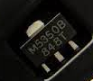 |
MST53XXB.pdf |
$0.1142 |
| Resistors | 31 | SMT resistors various ohms. | 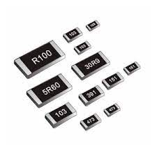 |
resistors.pdf |
~$0.04140 x 31 = 1.2834 |
| Choke | 1 | 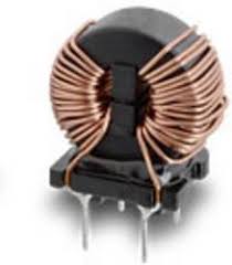 |
Choke.pdf |
$2.55000 |
|
| THT Capacitors | 4 |
|
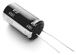 |
tht_cap.pdf |
|
| SMT Capacitors | 21 | 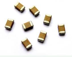 |
smt_cap.pdf |
$0.00466 x 21 = 0.09786 |
|
| Screw Terminals | 1 | 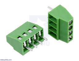 |
screw_terminal.pdf |
$0.6244 |
|
| Total | $12.54 |
After going through the table, it can be concluded that the device cost about ~$9.4 when the parts are purchaged in bulk quantity. That results in ~$3 of profit.
After dissecting the presented DC-DC buck-boost converter, I feel comfortable designing my bench power supply, during this journey, I was able to learn about various electronic components which I will be able to use in the future during my engineering
career.